You are here: Durability of Reinforced Concrete - Part 2
Please note that this paper is a continuation of Durability of Reinforced Concrete Part 1
British Standard 7973: 2001.
BS 7973 -1 contains full details of the product requirements for the spacers and chairs, and BS 7973 -2 specifies how they are to be used, including the tying of the reinforcement. Copies of BS 7973 Parts 1 and 2 are available from British Standards Institution, 389 Chiswick High Road, London, W4 4AL. Tel: 0208 996 9001 Price: BSI Members - £ 34.00 each Part; Non-members - £ 68.00 each Part.
Use of spacers and chairs.
Spacers are required to be fixed to the links, reinforcement or welded steel fabric nearest to the face of the concrete to which the cover is specified. If coloured, textured, profiled or exposed aggregate finishes are required the reinforcement can be spaced either off the opposite face, or by the use of chairs.
The use of spacers and chairs follows some very simple rules. As welded fabric and bar reinforcement behave differently under loading the rules for the use of spacers and chairs vary accordingly. Spacers are fixed to the reinforcement nearest to the surface of the concrete, (except for cementitious line spacers), i.e. fixed to the links in beams and columns. Chairs are fixed between layers of reinforcement,
(except for individual chairs), i.e. between the top and bottom layers of reinforcement in a slab, or the faces of a wall.
The general rule for spacers is that they shall be fixed to BAR REINFORCEMENT at centres not exceeding 50d where d is the size of the bar to which they are fixed, and in staggered rows. See Figure 1(a) in BS 7973 -2:2001.
The general rule for WELDED STEEL FABRIC is that spacers shall be fixed to the fabric at centres not exceeding 500mm in two directions at right angles. See Figure 1(b) in BS 7973 -2:2001.
There are additional rules for spacers at the edges of slabs, and in beams, columns and walls. See Figures 5, 7, 8 and 9 in BS 7973 -2:2001.
Chairs support the top reinforcement from the bottom reinforcement. They should be positioned at centres not exceeding 50d for BAR REINFORCEMENT or 500mm for WELDED STEEL FABRIC and be positioned directly above the spacers which support the bottom layer of reinforcement. The size of the top reinforcement governs the spacing of the chairs which then governs the spacing of the spacers.
Full details of the requirements for the positioning of spacers and chairs are contained in the Standard.
Getting the correct spacers and chairs.
For small projects the spacers and chairs can be added to the end of the reinforcement Schedule. This has proved to be a very effective way to ensure that the spacers and chairs are included in the project. The inclusion of the quantity of spacers in addition to the specification of the types is optional, but has been found to greatly assist builders working on smaller projects.
For larger projects it is also possible to produce a Schedule of the spacers and chairs required for the various elements of the structure, or to add the requirements into the Notes on the drawing. For example:-
- For beams; 25mm cover to bottom, sides and top; AN 1290 "A‟ spacers to BS 7973 –2:2001.
- For ground slabs with insulation below them; 40mm bottom cover; AN 1296 "A‟ spacers to BS 7973 -2: 2001 with B1394 bases.
- For suspended slabs with top and bottom reinforcement; 25mm bottom cover; AN 1290 "A‟ spacers to BS 7973 -2:2001,and 100mm high continuous wire chairs to BS 7973 -2:2001.
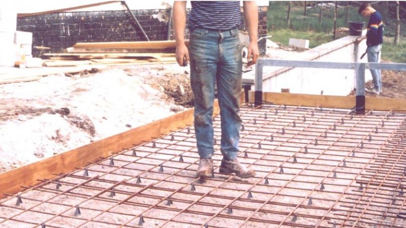
Spacers being fixed in accordance with BS 7973
Using BS 7973.
The provisions in the Standard have been developed over more than 30 years and used in actual structures for more than 25 years. The application of the requirements of BS 7973 is the cheapest and most sustainable way to ensure that the design life of the specified cover is achieved. Their use will ensure that the specified cover to the reinforcement will be achieved first time, every time. The provisions of BS 7973 have world-wide applications wherever reinforced concrete is used.
The requirements of BS 7973 can easily be implemented by:
- In the Specification add the text “Spacers and chairs shall comply with the requirements of British Standard 7973 -1: 2001, and be fixed in accordance with BS 7973 -2: 2001”.
- On each reinforced concrete drawing include the text “Spacers and chairs shall comply with the requirements of British Standard 7973 -1: 2001, and be fixed in accordance with BS 7973 -2: 2001, in particular Figures 1 to 9”.
- Select the correct type of spacers and chairs for the reinforcement and the intended use at the design stage.
- Either show the spacers and chairs on the drawings (for small projects) or use standard drawing based on the Figures in BS 7973 -2: 2001 (for larger projects), or specific reference can be made to the Figures in BS 7973 -2: 2001. For example, “Spacers for beams shall be positioned in accordance with Figure 7 of BS 7973 -2: 2001”. Similar text can be used for columns, slabs and walls.
- Check that the spacers and chairs that are supplied are as specified and in accordance with the requirements of BS 7973 -1:2001. Be aware that there are many non-compliant products on the market. A site visit is the best way to check this. Where a visit is not possible a risk assessment base approach is much better than nothing at all. The following requirements can be incorporated into the Specification so that the contractor is aware of them at the time of tender.
Whether or not you will be able to inspect the reinforcement on site before concreting check:-
- Before construction starts:
Ask the contractor to confirm in writing the specific spacers and chairs that he proposes to use. Ask for the manufacturer(s) details and the product reference numbers. Check what is proposed from the manufacturer(s) catalogues; and; - During construction:
Ask the contractor for a sample of each of the spacer and chair types that he is using to be delivered to your office. Check what is sent.
Ask for digital photographs of the reinforcement, spacers and chairs before concreting. These can be sent by email.
If the concrete has already been poured:
- After concreting:
Ask the contractor for samples of the spacers and chairs that were used and / or copies of the delivery notes / purchase receipts for the spacers and chairs. There are usually some samples left over after concreting. Look at record photographs of the work.
Summary.
The publication of BS 7973 is a major step forward to the achievement of the specified cover to the reinforcement in reinforced concrete structures. The provisions of BS 7973 have world-wide applications wherever reinforced concrete is used. It enables the specified cover to be achieved first time, every time. It is the cheapest and most sustainable way to ensure that the cover is achieved. This will ensure that the structural, durability and fire performance of buildings in respect of the cover to the reinforcement.
Worked examples of spacers and chairs for the design of new work.
1) Beam.
Consider a beam 500mm deep by 300mm wide. This is a "Normal‟ beam to BS 7973 – 2, Figure 7(c). It has 30mm cover to the sides and soffit. The main reinforcement is 25mm size and the links are 12mm size at 200mm centres. The spacers required would be "A‟ spacers, reference AN1292 in groups of four, fixed to the LINKS in the positions shown in BS 7973 –2, Figure 7(c). The spacing of the groups along the links would be at centres not exceeding 1000mm, (see BS 7973 –2, Figure 7(a)); therefore not exceeding every fifth link as the links are at 200mm centres along the beam.
2) Column.
Consider a 400mm square column 4.5m high. This is a „Small‟ column to BS 7973 –2, Figure 8(b). It has 30mm cover to the links. The main reinforcement is 25mm size and the links are 12mm size at 200mm centres. The spacers would be "A‟ spacers, reference AN1292 in groups of six, arranged as shown in BS 7973 –2, Figure 8(b). The spacing of the groups of spacers up the height of the column is governed by the size of the MAIN reinforcement. The groups of spacers should be located at the top, middle and bottom of the column and at centres up the column not exceeding 100 D where D is the size of the MAIN reinforcement. In this case the centres up the column would be 100 x 25 = 2500mm which means that groups of spacers fixed to the LINKS at the top, middle and bottom of the column are sufficient to comply with the Standard. This is usually the case for most columns.
3) Wall.
Consider a wall 250mm thick with 25mm cover to the reinforcement on each face. The reinforcement is A393 standard welded steel fabric comprising 10mm wires at 200m centres in each direction, with the outer wires being vertical on each face of the wall. The size of the chairs to be fixed between the welded steel fabric would therefore be 250 – (2 x 25) – (4 x 10) = 160mm. Therefore for vertical continuous chairs 150mm high ones would be selected. Chairs can be used horizontally along the length of a wall positioned between the OUTER layers of reinforcement. In this case the chairs would be 250 – (2 x 25) – (2 x 10) = 180mm, which is exactly a standard size. Therefore the designer has a choice of using 150mm high chairs used vertically or 180mm high chairs used horizontally. The preferred choice is to use the chairs vertically because this assists the placing of the concrete in the wall. The 10mm difference between the 160mm calculated size and the 150mm manufactured size gives 10mm of tolerance and ensures that the 25mm cover can be achieved for both faces of the wall. The spacers would be 25mm "A‟ spacers, reference AN 1290, fixed at 400mm centres horizontally (i.e. every other vertical wire) and at centres not exceeding 500mm vertically up the wires. The spacers and chairs should line up when viewed in elevation as shown in BS 7973 –2, Figure 9.
4) Suspended slab with top and bottom reinforcement – Example 1.
Slabs can have either bottom or top reinforcement only or have both top and bottom reinforcement. Slabs with bottom reinforcement only are illustrated in BS 7973 –2, Figure 1, and slabs with top reinforcement only are illustrated in BS 7973 -2, Figure 3. Slabs with both top and bottom reinforcement require both spacers and chairs. Consider a slab 250mm thick with 25mm cover to the reinforcement at the top and bottom faces. The reinforcement is 12mm size bar at 200mm centres each way in the bottom and 10mm size bar at 200mm centres each way in the top. The height of the chairs supporting the top reinforcement would be 250 – 25 – 25 - (2 x 12) – (2 x 10) = 156mm. Therefore use 150mm high continuous lattice or goalpost type chairs at centres not exceeding 50 x 10 = 500mm, in parallel rows.
The spacers would be 25mm "A‟ spacers, reference AN1290, at centres not exceeding 50 x 12 = 600 mm along the bars. Across the bars the 600mm centres would need to be reduced to match the centres of the chairs i.e. 500mm, but the reinforcement is at 200mm centres so the spacers would need to be fixed at 400mm centres across the bars, i.e. every other bar, and the spacing of the chairs reduced to 400mm
to line up with the spacers as shown in BS 7973 –2, Figure 2.
Note that the spacing of the chairs depends on the top reinforcement and the spacing may have to be reduced to ensure that the chairs line up with the centres of the spacers across the bottom reinforcement.
Spacers for the edges of the slab are shown in BS 7973 –2, Figure 5. The arrangement of the edge spacers depends on the detailing of the reinforcement at the edge of the slab.
5) Suspended slab with top and bottom reinforcement – Example 2.
Consider a suspended floor slab, 230mm thick with top and bottom reinforcement and 25mm top and bottom cover to the reinforcement.
Reinforcement
- Top Main Layer T1 16mm @ 200 centres. (1010 mm2/m).
- Top Distribution Layer T2 10mm @ 150 centres. (523 mm2/m).
- Bottom Distribution Layer B2 12mm @ 175 centres. (646 mm2/m).
- Bottom Main Layer B1 20mm @ 200 centres. (1570 mm2/m).
The continuous wire chairs required would be at centres not exceeding 50 x 10mm = 500mm. The height would be 230 – (2 x 25) – 16 – 10 – 12 – 20 = 122mm. Therefore use 120mm high continuous wire
chairs in rows at 500mm centres.
The spacers required would be at centres not exceeding 50 x 20mm = 1000mm along the bars and in theory every fifth bar across the bars (i.e. not exceeding 50d centres). However, the spacers need to be directly below the chairs. As the B1 bars are at 200mm centres the spacers and the chairs need to be at 400mm centres. The rows of spacers need to be staggered as shown in Figure 1(a) of BS 7973 -1: 2001.
Changing the reinforcement in layer T2 to 12mm @ 200 centres, (566 mm2/m), would enable the chairs to be at 600mm centres which would then increase the centres of the spacers on layer B1 to 600mm, and
be more economical.
Spacers for the edges of the slab are shown in BS 7973 –2:2001, Figure 5. The arrangement of the edge spacers depends on the detailing of the reinforcement at the edge of the slab.
If you need further assistance or advice please contact:-
Chris Shaw CEng FICE FIET MIStructE MCMI
Consultant
Chairman, BS 7973 committee
Email: echrisshaw@yahoo.co.uk
v0.4 02.04.2007
© C B Shaw 2007
For a list of Structural Engineers who can provide Design Calculation services click here.